Water structures Sheets (Dam Spillway Design, Complete Water Supply Treatment Plant)
1-Dam Spillway Design:
A spillway is a structure used to provide the controlled release of flows from a dam or levee into a downstream area, typically being the river that was dammed. In the UK they may be known as overflow channels. Spillways release floods so that the water does not overtop and damage or even destroy the dam. Except during flood periods, water does not normally flow over a spillway. In contrast, an intake is a structure used to release water on a regular basis for water supply, hydroelectricity generation, etc. Floodgates and fuse plugs may be designed into spillways to regulate water flow and dam height. Other uses of the term "spillway" include bypasses of dams or outlets of a channels used during highwater, and outlet channels carved through natural dams such as moraines.
Energy dissipation
As water passes over a spillway and down the chute, potential energy converts into increasing kinetic energy. Failure to dissipate the water's energy can lead to scouring and erosion at the dam's toe (base). This can cause spillway damage and undermine the dam's stability. The energy can be dissipated by addressing one or more parts of a spillway's design.
Steps - First, on the spillway surface itself by baffles and/or steps along the spillway.
Flip bucket - Second, at the base of a spillway, a flip bucket can create a hydraulic jump and deflect water upwards.
Ski jump - A ski jump can also direct water horizontally and eventually down into a plunge pool or two ski jumps can direct their water discharges to collide with one another.
Stilling basin - Third, a stilling basin at the terminus of a spillway serves to further dissipate energy and prevent erosion. They are usually filled with a relatively shallow depth of water and sometimes lined with concrete. A number of velocity-reducing components can be incorporated into the their design to include chute blocks, baffle blocks, wing walls, surface boils or an end sill.
2-Complete Water Supply Treatment Plant:
Complete Water Supply Treatment Plant
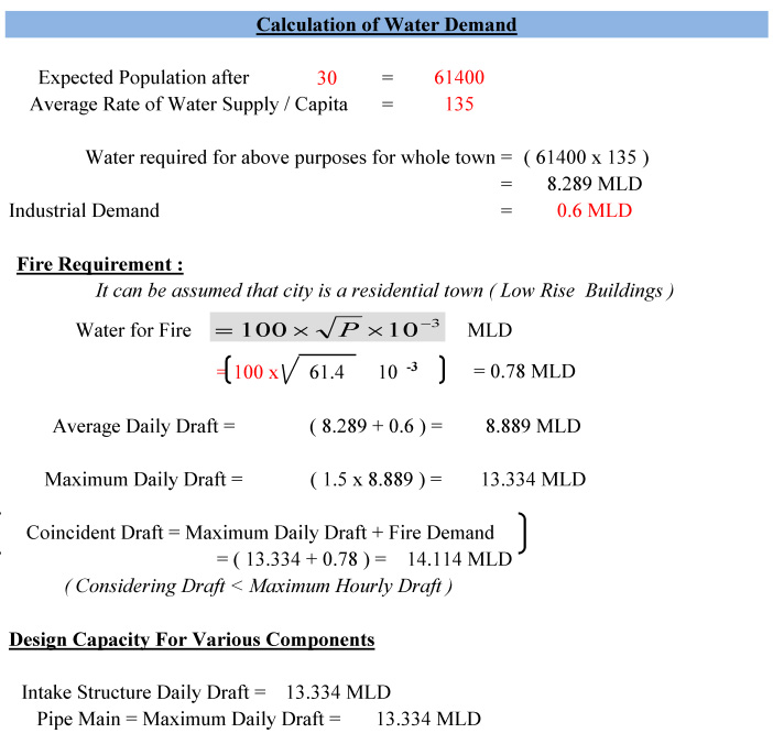
Calculation of Water Demand
Physical & Chemical Standards Of Water
Comparison of Given Data & Standard Data and Treatment Proposed
Design of Intake Well
Design of Pen Stock & Bell Mouth Strainer
Design of Gravity Main
Design of Jack Well
Design Of Pumping System
Design of Rising Main
Treatment Units - Design Of Aeration Unit
Design Of Chemical House & Calculation Of Chemical Dose
Lime - Soda Process
Design Criteria for Mechanical Rapid Mix Unit
Design Of Clariflocculator
Design Of Rapid Gravity Filter
Design Of Disinfection Unit
 $ 38
$ 38